
Hydraulic Engineering & Machining
Technical & Scientific Study: Tipping Kinematics, Cylinder Sizing, and NR-12 Safety in Hydraulic Swarf Tippers
An engineering analysis of hydromechanics applied to automated machining waste disposal, cutting fluid recovery, and ergonomic risk mitigation.
Application & Hydraulic Engineering
INCOFORK Technical Department
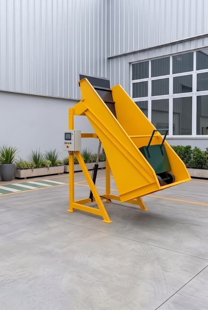
Abstract
This study investigates the mechanical-hydraulic principles and safety standards governing the design of autonomous industrial chip discharge stations. It examines why 135° tipping is indispensable for dislodging tangled, oil-soaked metal shavings, hydrostatic modeling of the actuator at 100 bar nominal pressure, descent deceleration via a 3/8" BSP flow control valve, and the integration of electrical and mechanical safety devices pursuant to NR-12 and NR-10. It demonstrates that replacing manual dumping or forklifts reduces cycle times by up to 70% while enabling gravity reclamation of reusable cutting fluids.
Table of Contents
- 1. Introduction: The Metal Chip Logistics Bottleneck in Manufacturing
- 2. Tipping Kinematics and the 135° Discharge Angle
- 3. Hydraulic Cylinder Sizing, Pressure, and Moment Curve
- 4. Deceleration Control: The 3/8" BSP Flow Control Throttle Valve
- 5. Operational Safety and Compliance with NR-12 & NR-10 Standards
- 6. Sustainability and Reclaiming Cutting Fluid & Coolant
- 7. Comparative Operational Efficiency Analysis
- 8. Technical Conclusion and Economic Viability
- Frequently Asked Questions (FAQ)
1. Introduction: The Metal Chip Logistics Bottleneck in Manufacturing
In CNC machining centers, automatic lathes, and high-speed milling machines, the continuous generation of metal chips and swarf is one of the most critical productivity bottlenecks on the shop floor. Metal shavings—whether carbon steel, cast iron, aluminum, or specialty alloys—feature high apparent volume, sharp edges, and surface saturation with lubricating oils and water-soluble cutting fluids.
Historically, shop-floor chip disposal routines have alternated between two unfavorable practices:
1. Manual dumping of drums or carts: A physically demanding method that exposes operators to severe risks of lower back pain and musculoskeletal disorders (RSI/WMSD, NR-17), in addition to frequent lacerations from sharp metal splinters and prolonged skin exposure to contaminated cutting oils.
2. Direct reliance on forklifts: Transporting hoppers or hydraulic scoops attached to forklift forks creates heavy traffic in narrow machine-shop aisles. This causes recurring waiting times, idles machine tools while carts await pickup, and increases collision risks inside the facility.
Establishing dedicated stationary discharge stations, such as the MJI-TC 500 Hydraulic Chip Tipper from INCOFORK industrial equipment, eliminates this bottleneck by decentralizing waste disposal—enabling the cell operators themselves to empty carts with complete autonomy, speed, and safety.
Proven Operational Impact
Ergonomic and productivity audits in metalworking plants show that makeshift manual handling of chip bins is among the leading causes of musculoskeletal work absences in machining departments. Concurrently, an estimated 10% to 15% of total plant cutting fluid volume is inadvertently discarded with metal scrap due to inadequate gravity drainage.
2. Tipping Kinematics and the 135° Discharge Angle
Unlike granular bulk materials or free-flowing powders, machining swarf acts as a highly cohesive mass. The mechanical intermeshing of metal ribbons and tight spirals, combined with the surface tension of soluble oil films, creates dense, tangled blocks inside storage bins.
In conventional dump hoppers limited to 45° to 60° rotation (typical forklift front-attachment geometry), internal friction frequently retains up to 30% of the scrap at the bottom. This forces operators to hammer the structure or use manual pry bars to loosen tangled chips—introducing high safety risks.
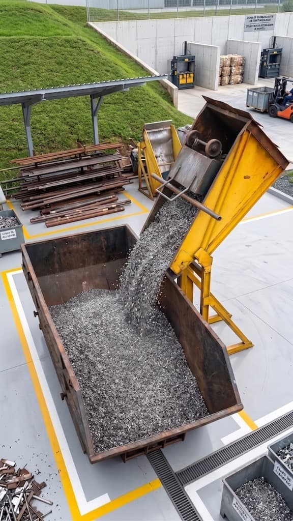
To achieve 100% gravitational discharge without direct human intervention, the tipping cradle kinematics of the MJI-TC 500 Tipper were engineered to achieve a vertical rotation of up to 135° of inclination.
Upon exceeding 90° and reaching the 135° angular threshold:
3. Hydraulic Cylinder Sizing, Pressure, and Moment Curve
Power transmission in the tipper is powered by an autonomous electro-hydraulic power unit mounted on a unified chassis, designed by the INCOFORK engineering team. The power pack is equipped with a 1.5 HP (1.1 kW) three-phase electric motor and a gear pump calibrated to 5.7 liters per minute, drawing from an 8-liter oil reservoir with ISO VG 68 viscosity fluid.
The hydraulic system operates with a relief valve setting of 100 bar, delivering optimal power density to smoothly lift payloads up to 500 kg (combined mass of the chip cart and accumulated scrap).
Mechanical demand on the cylinder is not uniform across the stroke: resisting torque peaks during the initial 25° to 30° of ascent, when the horizontal moment arm of the load's center of gravity reaches its maximum perpendicular distance from the fixed rotational pivot of the cradle.
Hydrostatic Formula & Design Load Factor
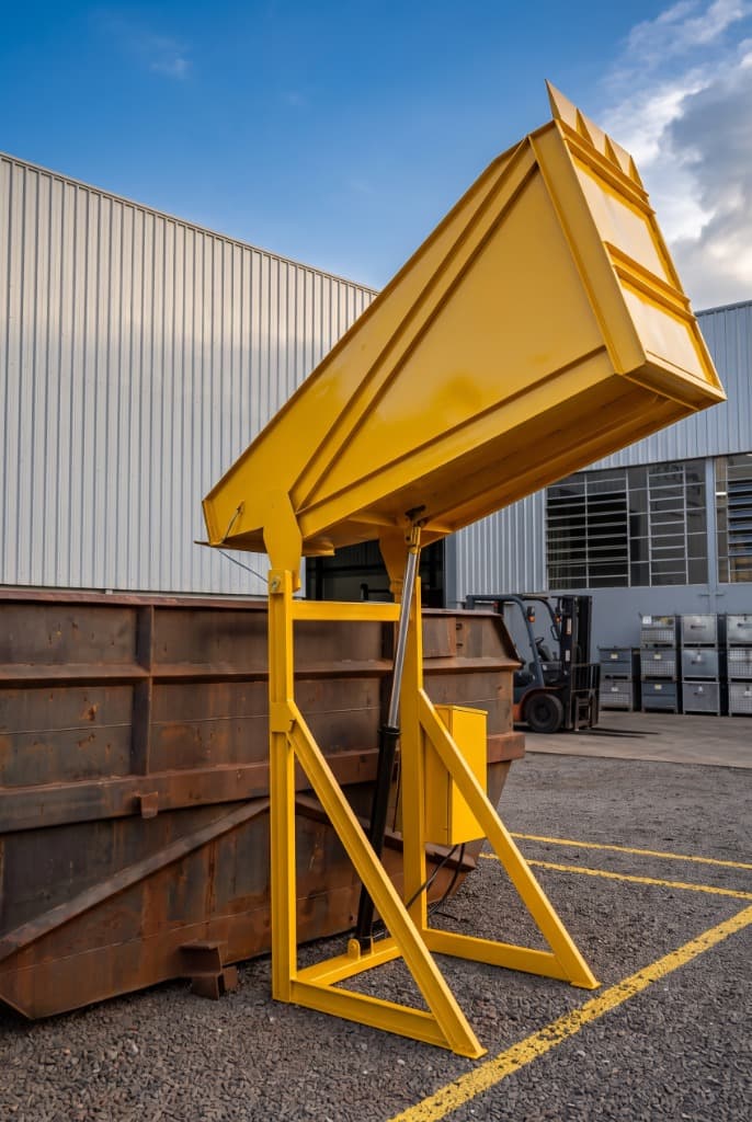
4. Deceleration Control: The 3/8" BSP Flow Control Throttle Valve
One of the most severe mechanical hazards in gravity-assisted tipping equipment is uncontrolled return speed during descent. If hydraulic oil exits the cylinder chamber without hydrodynamic cushioning, gravity accelerates the cradle structure, creating violent impacts against frame stop bumpers, premature joint deformation, and extreme hydraulic shock waves (water hammer) in return lines.
To eliminate this risk, INCOFORK engineering incorporated a unidirectional flow control valve (3/8" BSP) with integrated reverse check, coupled with an HDM140 open-center directional control valve:
1. Lifting Phase (Cylinder Extension): Pumped oil volume (5.7 L/min) bypasses flow restrictions through the check valve seat, directing full hydraulic power to hoist the payload smoothly.
2. Lowering Phase (Dampened Retraction): During descent, the internal check closes, forcing fluid through the calibrated needle orifice (meter-out principle). This throttling generates progressive hydrostatic backpressure that dampens free-fall acceleration, ensuring a strictly uniform and controlled descent speed.
3. Emergency Stability: The reverse check design and calibrated throttling prevent abrupt free-fall drops even in the event of sudden power loss to the motor pump unit, holding the cradle suspended safely.
Extended Structural Integrity
By converting descending kinetic energy into gentle thermal dissipation within the hydraulic fluid via calibrated throttling, end-of-stroke mechanical shocks are eliminated. This significantly prolongs the service life of pivot bearing pins, heat-treated steel bushings, and structural welds.
5. Operational Safety and Compliance with NR-12 & NR-10 Standards
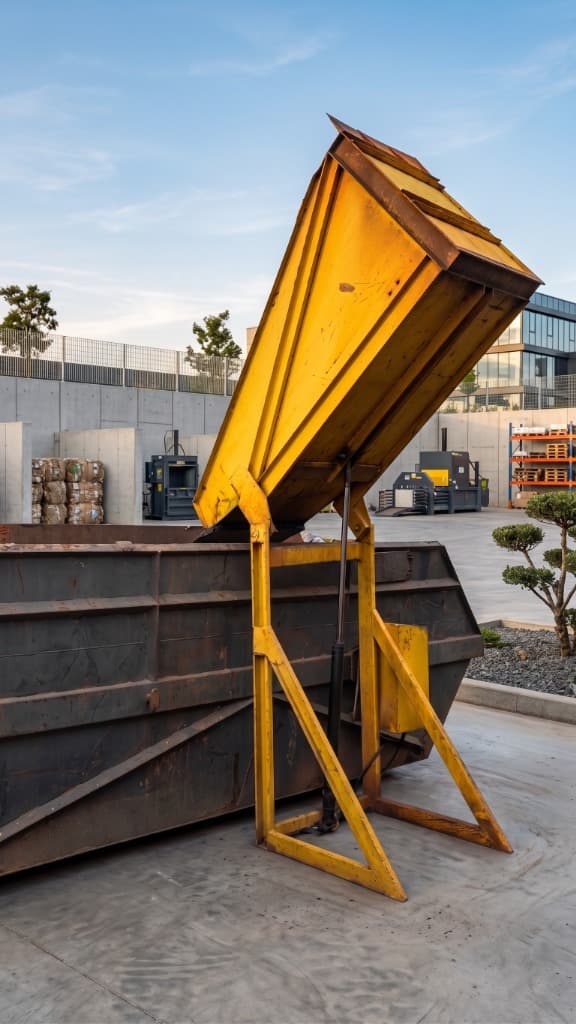
The structural design of the stationary tipper incorporates technical guidelines from Brazilian safety regulations NR-12 (Machinery and Equipment Safety), NR-10 (Electrical Safety), and ergonomic guidelines from NR-17—benchmarks built into all INCOFORK attachments and industrial equipment:
6. Sustainability and Reclaiming Cutting Fluid & Coolant
Environmental and financial management in precision machining facilities demands rigorous conservation of chemical inputs. Metal chips exiting machine tools carry micro-droplets and adhering films of coolant emulsion within their geometry. Accumulated over working shifts, this represents hundreds of liters of high-grade cutting oil lost to disposal.
By placing carts in the MJI-TC 500 Tipper and pausing at 135° for a few moments, shops unlock immediate benefits:
7. Comparative Operational Efficiency Analysis
The following comparison details the operational, ergonomic, and economic differences between three common shop-floor chip handling approaches:
Operational Performance Comparison Table
8. Technical Conclusion and Economic Viability
Modernizing internal chip logistics in machining departments goes far beyond shop-floor tidiness: it directly drives machine uptime, workforce ergonomics, and plant operational profitability.
Implementing a stationary tipping station with 135° rotational kinematics, an actuator engineered with a 5:1 dynamic safety margin, and 3/8" BSP meter-out hydraulic deceleration dampening definitively solves the trade-off between cycle speed, mechanical longevity, and regulatory safety compliance under NR-12 and NR-10.
The INCOFORK MJI-TC 500 Hydraulic Chip Tipper exemplifies this synergy of heavy structural engineering and precision fluid power. To determine the ideal material handling configuration for your facility's layout, contact our application engineering specialists.
Frequently Asked Questions (FAQ)
Engineering technical answers regarding kinematics, hydraulic circuits, NR-12/NR-10 safety and shop floor integration.
1Why is a 135° tipping angle required for metal chips instead of 45° or 60° as used in standard dump hoppers?
Unlike free-flowing bulk goods like grains or dry sand, machining scrap exhibits severe mechanical interlocking among its coils and strong adhesive cohesion due to coolant oil viscosity. At conventional angles of 45° to 60°, up to 30% of the scrap remains trapped at the bottom of the container. By rotating to 135°, the cart base is inverted past the vertical plane, allowing gravity to overcome fluid adhesion and ensure complete, self-clearing evacuation without manual intervention.
2What is the function of the 3/8" BSP flow control valve with integrated check in the hydraulic circuit?
It acts as a dynamic deceleration damping mechanism (meter-out) during descent. When lifting, oil bypasses restrictions freely through the check valve, supplying full power to raise the load. During lowering, return flow is forced through a calibrated micrometer needle orifice, creating hydrostatic backpressure in the cylinder chamber. This prevents gravity from accelerating the cradle downwards, eliminating violent mechanical shocks against the chassis and preventing pressure surges (hydraulic shock) in the tubing.
3Does the chip tipper comply with all NR-12 and NR-10 regulatory safety requirements?
Yes. The system incorporates positive mechanical wheel locks that retain the cart's casters throughout the 135° tilting cycle, an electromechanical limit switch (1NO+1NC) with positive contact opening to limit travel, an industrial sealed electrical enclosure with hold-to-run push buttons (movement only occurs while actively pressed), a mechanical latching emergency mushroom button, and a lockable master disconnect switch for LOTO procedures.
4Does the equipment require compressed air or external factory hydraulic lines?
No. The MJI-TC 500 Tipper is 100% self-contained. It features its own integrated electro-hydraulic power unit consisting of a 1.5 HP (1.1 kW) three-phase electric motor, gear pump (5.7 L/min at 100 bar), internal 8-liter hydraulic fluid reservoir (ISO VG 68), and manifold valve block. Installation requires only a standard three-phase electrical drop (220V or 380V) and anchoring the base plates to the floor.
5How does the tipper assist in recovering cutting fluid and water-soluble oils?
While the cart is held inverted at 135°, free coolant drains by gravity through the front discharge chute into drums or sump troughs connected to centralized decanters and filtration units. Beyond recovering costly cutting emulsions, drier swarf yields less fluid weight penalty and earns higher market scrap value from steel mills.
6Can the tilting cradle be customized to accommodate the factory's existing cart fleet?
Yes. Although the tipper is dimensionally optimized for seamless operation with the INCOFORK MJI-CR200 Chip Cart, INCOFORK engineering customizes cradle dimensions and wheel retention fixtures to fit client pre-existing container widths and track dimensions.
7What is the total disposal cycle time with the autonomous tipper?
The entire cycle—cart positioning and locking, smooth 135° tipping, instant scrap discharge, and cushioned return to starting position—takes under 45 seconds. The task is handled directly by the CNC cell operator next to their workstation, eliminating all waiting time for forklift drivers.
8What are the primary preventive maintenance requirements for the equipment?
System maintenance is straightforward and low-cost: periodic visual checks of hydraulic fluid level and clarity on the reservoir sight gauge, biannual greasing of cradle pivot grease zerks, checking base anchor bolt torque, and monthly functional testing of the emergency stop switch and travel limit switch.
References & Standards
- INTERNATIONAL ORGANIZATION FOR STANDARDIZATION. ISO 4413: Hydraulic fluid power — General rules and safety requirements for systems and their components. Geneva: ISO, 2010.
- BRAZILIAN MINISTRY OF LABOUR AND EMPLOYMENT. Regulatory Standard No. 12 (NR-12): Safety in Machinery and Equipment. Brasília: MTE, 2019.
- BRAZILIAN MINISTRY OF LABOUR AND EMPLOYMENT. Regulatory Standard No. 10 (NR-10): Safety in Electrical Installations and Services. Brasília: MTE, 2004.
- PARKER HANNIFIN CORP. Industrial Hydraulic Technology: Bulletin 0232-B1. Cleveland: Parker Fluid Power Training, 2018.
- DINIZ, A. E.; MARCONDES, F. C.; COPPINI, N. L. Machining Technology of Materials. 9th ed. São Paulo: Artliber Editora, 2014.
Related Equipment
Hydraulic Chip Tipper MJI-TC 500
Autonomous station with 1.5 HP electro-hydraulic power unit, high-pressure cylinder (100 bar) with deceleration dampening via 3/8" valve, 135° tipping cradle, and full NR-10/NR-12 compliance.